| Author |
Topic |
|
|
KnowledgeBase
296 Posts |
 Posted - 01 Mar 2002 : 16:30:26 Posted - 01 Mar 2002 : 16:30:26


|
Bitsy User's Manual (PDF)
Changes, updates and errata will appear as replies to this topic as they become available.
Bitsy evaluation systems include a Bitsy Personality Board that breaks out and expands many of the functions available on the Bitsy.
------------------
ADS Knowledge Base
Edited by akidder 22-May-02: Added note about Bitsy Personality Board
Did you know?
You can get automatic email notifications when this, or any Topic is changed or replied to. Simply click the "Subscribe" icon ( ) on the Topic List page (back one from here) on the right side of the Topic to which you would like to subscribe. ) on the Topic List page (back one from here) on the right side of the Topic to which you would like to subscribe.
You can cancel or manage your subscriptions at any time from the "My Subscriptions" menu item at the upper left of any Forum page. |
|
|
akidder
1519 Posts |
 Posted - 29 Mar 2002 : 17:33:22 Posted - 29 Mar 2002 : 17:33:22


|
#BitsyC_signal_changes
Errata/Addenda: J3 and J10 signals
Several of the signals on Bitsy connectors J3 and J10 changed between revisions B and C of the Bitsy. The following tables illustrate these changes:
| J3 pin | from | to | | 35 | SMTIO2 (PC6) | AC97 codec: data in | | 36 | n/c | GND | | 37 | SMTIO3 (PC7) | AC97 codec: data out | | 39 | n/c | AC97 codec: BCLK |
| 43 | n/c | AC97 codec: WS |
| J10 pin | from | to | | 11 | n/c | SMTIO2 (PC6) |
| 49 | n/c | SMTIO3 (PC7) |
The following is a table of how ADSmartIO signals are mapped on the Bitsy (AVR port names are in parentheses):
| J10 pin | description | | 11 | SMTIO2 (PC6) |
| 13 | SMTIO1 (PD1) | | 15 | SMTIO0 (PD0) | | 17 | ROW0 (PC0) | | 19 | ROW1 (PC1) | | 21 | ROW2 (PC2) | | 23 | ROW3 (PC3) | | 25 | ROW4 (PC4) | | 27 | COL0 (PA0) | | 29 | COL1 (PA1) | | 31 | COL2 (PA2) | | 33 | COL3 (PA3) | | 49 | SMTIO3 (PC7) |
As a result of these changes, the Rev 1 connector board cannot make use of PC6 and PC7 with Rev C Bitsy systems. Leave the "PC6" and "PC7" pins on the connector board J31 header unconnected to prevent interference with the codec signals. (see also ADSmartIO)
Edited by akidder 02-Apr-2002: Correct J3 entries
Edited by akidder 16-Apr-2002: Add note about connector board
Edited by akidder 02-Jul-2002: Add "from" columns; separate ADSmartIO table from changes; clarify wording in summary about PC6 and PC7 |
 |
|
|
akidder
1519 Posts |
 Posted - 29 Mar 2002 : 17:40:40 Posted - 29 Mar 2002 : 17:40:40


|
#bitsy_power_addendum
Addendum: Bitsy Power
Power Consumption
Below is a table that lists power consumption of the Bitsy at 6, 9 and 12V at four different CPU activity levels. These specs were not available when the first revision of the user's manual was released.
Bitsy power consumption (pdf, 1pp)
Externally Available Voltages
Total current that may be drawn from the 5V and 3.3V power supplies is currently rated at 500mA each. Make sure to account for the draw of your display, backlight and PCMCIA cards when adding up your power budget.
|
 |
|
|
KnowledgeBase
296 Posts |
 Posted - 07 Jun 2002 : 09:23:27 Posted - 07 Jun 2002 : 09:23:27


|
The 3V battery input on J3.50 is not recommended for powering the system when asleep.
The reasons are the same as for the Graphics Client Plus and Graphics Master. Please refer to this updated information for background information.
If you want to supply backup battery power to your system, consider using the VBATT inputs. See this recent discussion for further details.
------------------
ADS Knowledge Base |
 |
|
|
akidder
1519 Posts |
|
|
akidder
1519 Posts |
 Posted - 03 Jul 2002 : 09:41:49 Posted - 03 Jul 2002 : 09:41:49


|
Erratum: "VEE Select" Header
The "Flat Panel VEE Select" header should be labeled as JP5 in the user's manual. It is incorrectly listed as J7. |
 |
|
|
akidder
1519 Posts |
 Posted - 09 Jul 2002 : 11:46:12 Posted - 09 Jul 2002 : 11:46:12


|
Additional USB Components for Downstream Devices
Section 4.1.4 in the manual refers to additional components to connect to USB downstream devices. We've posted information about those components at this topic. |
 |
|
|
akidder
1519 Posts |
 Posted - 21 Aug 2002 : 12:02:47 Posted - 21 Aug 2002 : 12:02:47


|
Bitsy Downstream USB
If you have had a Bitsy for a while but are having trouble with downstream USB devices, take a look at this post for information about a hardware change that may need to be made to your system to improve operation.
|
 |
|
|
akidder
1519 Posts |
 Posted - 30 Aug 2002 : 15:44:34 Posted - 30 Aug 2002 : 15:44:34


|
#JP5
Addendum: Vee Selector (J7/JP5)
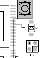
The rev. C Bitsy renames Vee selector J7 to JP5 and moves it close to the LED on the edge of the board. Pin numbering is as shown:

Note that Bitsy systems must be factory configured to support Vee, so most customers won't change the setting of JP5.
|
 |
|
|
akidder
1519 Posts |
 Posted - 01 Nov 2002 : 13:02:06 Posted - 01 Nov 2002 : 13:02:06


|
#stereo_audio
Addendum: EXT_IRQ2 and AMP_SDWN Signals
The AMP_SDWN signal(at J3.8) controls power to the Bitsy stereo audio amplifiers. When this input is set to 3.3V, the amplifiers are turned off and the Bitsy has no stereo audio output. This mode conserves power when stereo audio is not needed.
In rev A Bitsy systems, the AMP_SDWN signal is pulled down to ground on the board. This leaves the the audio amplifiers turned on unless explicitly disabled by an external input to AMP_SDWN.
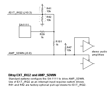
In revisions B and later, the Bitsy controls AMP_SDWN automatically using a GPIO from the SA-1111. However, that SA-1111 signal is also connected to the EXT_IRQ2 line(at J10.3), as shown in the following diagram.

Standard Bitsy systems currently connect the EXT_IRQ2 and AMP_SDWN signals together through R181. The SA-1111 configures the EXT_IRQ2 line as an output to control AMP_SDWN, so EXT_IRQ2 should not be used as an interrupt input on standard Bitsy systems.
The Bitsy has several other external interrupt sources (RqOnOff, CardBIRQ and EXT_IRQ1). If your application requires use of EXT_IRQ2 as an input, contact our Sales Group with your requirements.
|
 |
|
|
akidder
1519 Posts |
 Posted - 01 Nov 2002 : 14:50:54 Posted - 01 Nov 2002 : 14:50:54


|
#stereo_audio
Addendum: Stereo Audio Status and Control Signals
The Bitsy includes several signals for status and control of the UDA1341 stereo codec. Details about these signals are provided below. All signals are 3.3V CMOS logic. Digital outputs can source or sink up to 2mA.- AGCSTAT (J3.4)
Output from UDA1341.AGCSTAT.
The AGCSTAT signal is HIGH when the gain level of the automatic gain control(AGC) is below 8 dB. It's desirable to have the AGC run at higher levels to prevent signal saturation. The AGCSTAT signal can be used to drive an LED for user intervention or to tell the application to reduce the gain of the programmable gain amplifier(PGA). The PGA can be set in 6dB steps from -3 to 27dB; the AGC has a range of 30dB in 0.5dB steps.
- CODEC_OFL (J3.6)
Output from UDA1341.OVERFL
The CODEC_OFL signal indicates when output data from either channel exceeds -1 dB of the maximum possible digital swing. When this condition occurs, the CODEC_OFL output is HIGH for at least 512*fs cycles, where fs is the codec sample rate. It remains high as long as the error condition persists. This output can be used to drive an LED or otherwise signal that signal distortion is occurring or about to occur.
- AMP_SDWN (J3.8)
Shuts down output amplifiers (not a UDA1341 signal). See details above.
- QMUTE (J3.10)
Input to UDA1341.QMUTE
A HIGH on this input mutes the output of the codec. Use AMP_SDWN to control the output amplifiers.
|
 |
|
|
akidder
1519 Posts |
 Posted - 18 Dec 2002 : 15:35:54 Posted - 18 Dec 2002 : 15:35:54


|
#Bitsy_reset
Bitsy Erratum: System Reset
Under some conditions, the Bitsy hardware reset button will not reset the system. This occurs if a flash write operation is in progress when the button is depressed or the \Reset line is asserted. If this combination of events occurs, the system will not boot and must be power-cycled to restart.
This is an architectural issue with the Bitsy and does not apply to the Bitsy Plus, BitsyX and other ADS products. |
 |
|
|
akidder
1519 Posts |
 Posted - 12 Mar 2003 : 14:52:39 Posted - 12 Mar 2003 : 14:52:39


|
#RL_UD
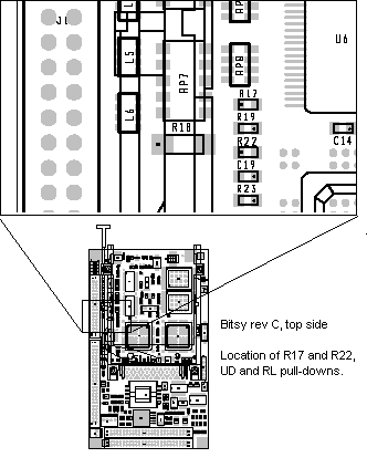
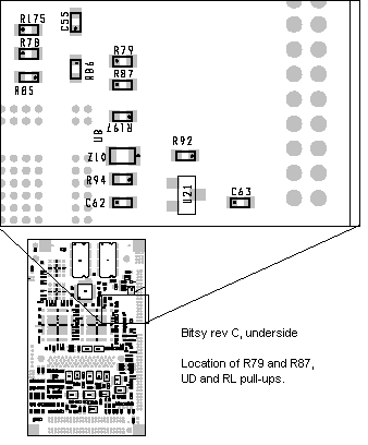
Addendum: Location of Display RL and UD resistors
Some displays support flipping the LCD display vertically and/or horizontally (see topic 485 for further details).
The RL and UD signals to the display can either be hard-wired in the display cable to the panel voltage(PNL_PWR) or ground, or they can be connected to the PNL_RL and PNL_UD signals.
If you choose connect the PNL_RL and PNL_UD signals, your Bitsy must have a couple pull-up or pull-down resistors populated for the display you are using.
To determine how the resistors are populated on your system, consult the following diagrams:

 |
 |
|
| |
Topic |
|